General
RGB line follower sensor module, which is idesigned specifically for line-following car matches, has 4 RGB supplement lamps and 4 light-sensitive receivers. The module applies to line following for either light-colored tracks on dark backgrounds, or dark tracks on light-colored backgrounds. All kinds of RGB line following modules are applicable, as long as the grey scale of the chromatic aberration between the background and the track is higher than the threshold (the higher the chromatic aberration, the better the line following performance). The module is characterized by fast detection, field learning function through keys and excellent adaptability. A blue-white labeled interface is equipped, indicating that it is a dual-digital, I2C interface that needs to be connected to the mainboard with a blue-white marking interface.
Technical Specification
● Operating voltage: 5V DC
● Operating temperature: 0 ºC~70 ºC
● Detection height: it is suggested that the sensor is 5mm~15mm from the track, depending on material of the track and illumination.
● Signal mode: I2C communication (corresponding to the blue-white label)
● Dimensions: 48 x 72 x 26.5 mm (LxWxH)
Functional Characteristics
● Arduino IDE programmable, with runtime library to simplify programming;
● Four LEDs for feedback of line-following and learning of new surroundings;
● RJ25 interface for convenient connection;
● Suitable for metal parts of Makeblock DIY platform: the white area on the module is the reference area in contact with metal beams;
● Modularized installation, compatible with LEGO;
● Equipped with interfaces compatible with most Arduino control boards;
● Field learning function: identifying and recording background of the field and color of the route;
● Supporting eeprom storage: data learned will be stored in eeprom, preventing data loss in case of power failure;
● Colors of RGB supplement lamps switchable: currently 3 colors switchable (read, green and blue), by pressing the switching key for 2 seconds;
● Sensitivity of line-following is adjustable;
● Reverse polarity protection, protecting IC in case of reverse polarity;
● Up to 4 line following sensors available on one main board.
Definitions of Pins
The RGB line follower module has a 6-pin interface, each pin has the function below:
| S/N | Pin | Function |
|---|---|---|
| 1 | SDA | I2C data interface |
| 2 | SCL | I2C clock interface |
| 3 | VCC | Power line |
| 4 | GND | Ground line |
| 5 | S2 | I2C address assignment port |
| 6 | S1 | 2C address assignment port |
Connection
● RJ25 Connection
Since the RGB line sensor module interface is blue-white, when using the RJ25 interface, it needs to be connected to the interface with the blue and white interfaces on the main control board. Taking Makeblock MegaPi as an example, you can connect to interfaces 5, 6, 7, and 8, as shown in the following figure: 
● Connection with Dupont line
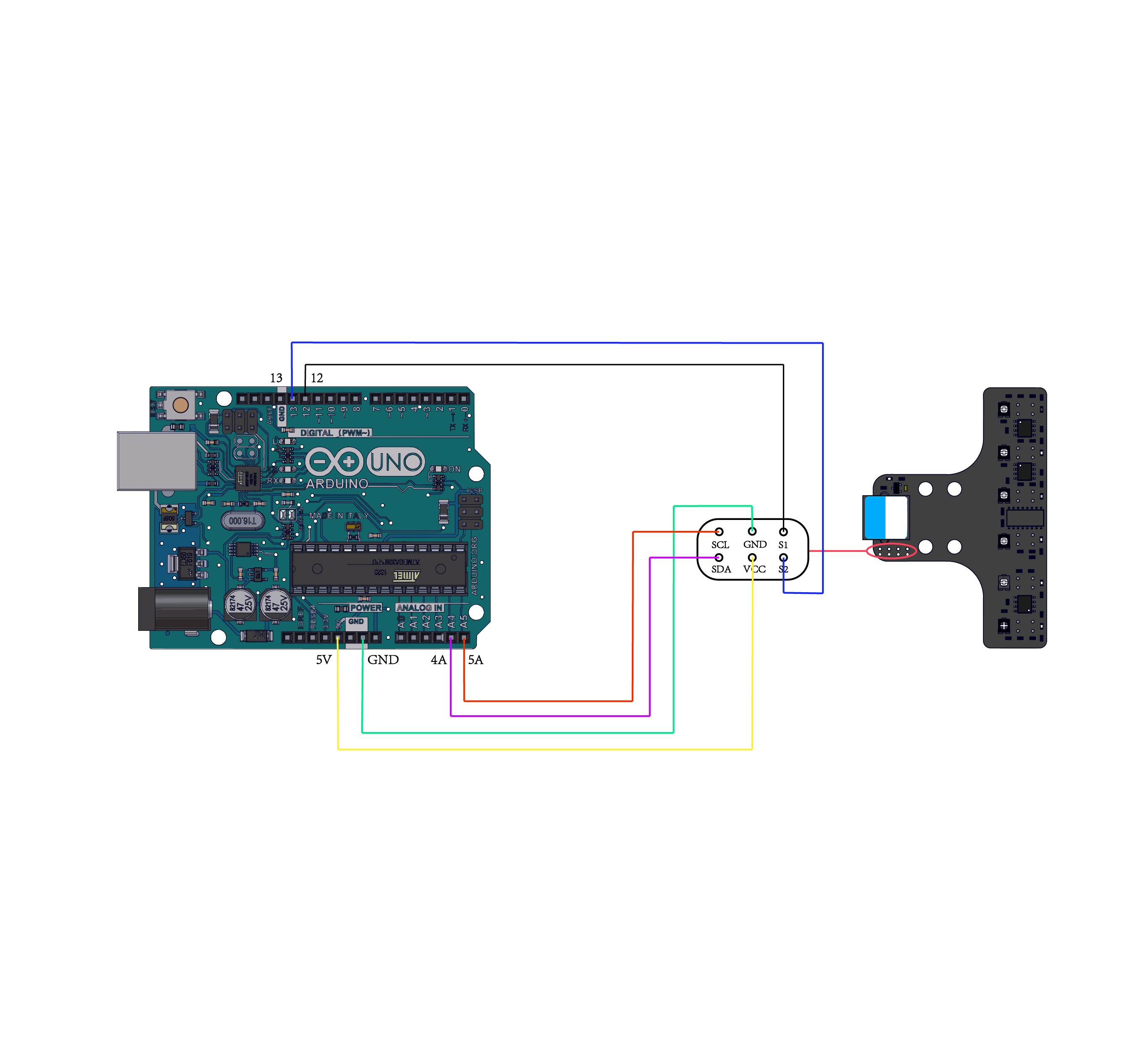
When using a DuPont cable to connect to the Arduino Uno mainboard, the A0 pin of the module needs to be connected to the ANALOG port as shown below:

Learning methods
In case of any change to the field, the surroundings or location where the RGB sensor is installed, it is suggested to start learning again. The data learned will be stored in eeprom, avoiding data loss in case of power failure. The learning process includes 4 steps::
1. Adjusting colors of supplement lamps: select suitable colors of the supplement lamps by long pressing the switching key according to colors of the field background and the line.
2. Learning color of the background: install the RGB sensor in position, face the 4 RGB lamps right against the background, and click the key to make the 4 LEDs flash slowly. Learning will finish in 2~3 seconds, upon which the LEDs will stop flashing.
3. Learning color of the track: install the RGB sensor in position, make the 4 RGB lights right against the track, and double-click the key to make the 4 LEDs flashing slowly. Learning will finish in 2~3 seconds, upon which the LEDs will stop flashing.
4. Test and confirmation: keep the module in position, and adjust locations of the 4 sensors, to make sure they can detect colors of the background and the line properly. When detecting the background, LED of corresponding sensor will be on; and when detecting the line, the corresponding LED will be off.
Programming
● Arduino Programming
When conducting Arduino programming, Makeblock-Library-master shall be called to control the RGB line follower sensor.
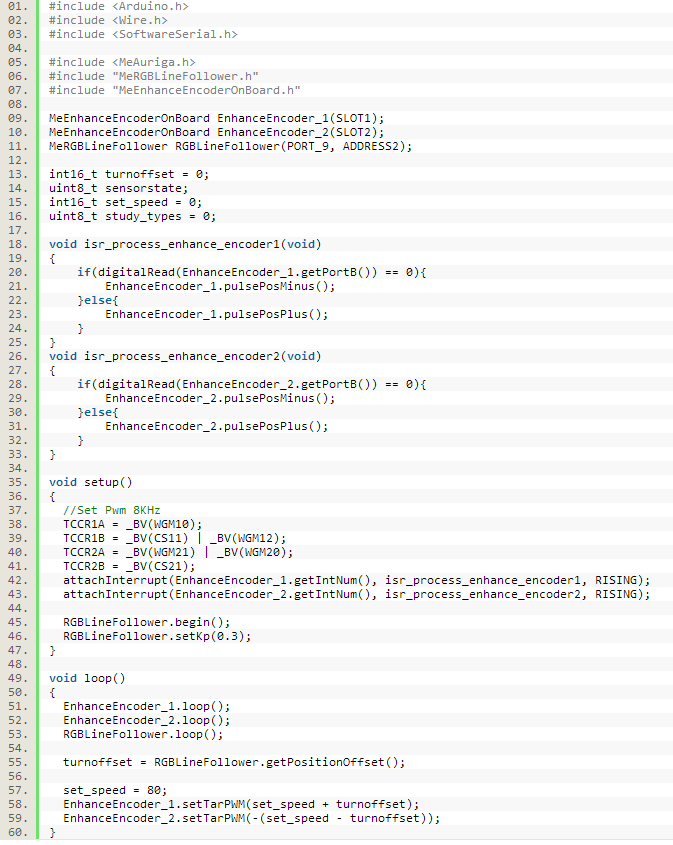
Two enhanced 180-encoded motors are used for line-following control. Source files “MeRGBLineFollower” and “MeEnhanceEncoderOnBoard” must be included in the root directory of project file, as follows:

“MeRGBLineFollower180motorAuriga.ino” is an example of line following, based on Auriga control board, with 180-encoded motor as chassis. The following codes are used:

List of Main Functions and Features of RGB Line Follower Sensor
| Function | Features |
|---|---|
| void setKp(float value) | Setting line following sensitivity, which is used for adjusting line following response speed. The larger the value is,more sensitive it turns. |
| int16_t getPositionOffset(void) | Obtaining offset of the sensor from the track. The output is taken as the product of the line following sensitivity Kp and the analog value resulted from fusion algorithm of the 4 sensors, ranging from -512 to 512. If it is larger than 0, it means that the line deflects to RGB4. The larger the value, the higher the offset. If it is smaller than 0, it means that the line deflects to RGB1. The greater the negative value, the higher the offset. |
| uint8_t getPositionState(void) | As shown in the figure, bit0~bit3 represent RGB4, RGB3, RGB2 and RGB1 from left to right respectively. “1” means that the background is detected (corresponding LED is on), while “0” means that the line is detected (corresponding LED is off). “0000” means that all the 4 sensors detect the line (all the LEDs are off), with 0 returned; “0111” means that the 4 sensors from left to right detect “line”, “background”, “background” and “background” respectively (the LEDs are off, on, on and on), with 7 returned; “0011” means that the 4 sensors from left to right detect “line”, “line”, “background” and “background” respectively (the LEDs are off, off, on and on), with 3 returned. |
| uint8_t getStudyTypes(void) | Obtaining learning status of the RGB sensor: 0-not learning, 1-learning background color, 2-learning track color |
● mBlock programming
The RGB line follower sensor is mBlock programmable, but “RGBLineFollower “is necessary to be installed. Besides, if 180-encoded motor is used as the chassis, “EnhanceEncoderOnBoard ” enhanced encoding motor is also needed.。
How to install the plug-ins: launch mBlock software→ Extension → Extension Manager → Find plug-in packages “RGBLineFollower’ and “EnhanceEncoderOnBoard” → Download the plug-in packages. Now, blocks as below will appear:

Introduction to the blocks:
Interface: Port1 ~Port12
Address: add1~add4 (0 ~ 3). Any port can be bound to any address, but one port of all related blocks in one program can only be bound to a unique address, and each address corresponds to a unique RGB line following module.
| Statement block | Description |
|---|---|
| Setting line following sensitivity, which is used for adjusting line following response speed. The larger the value is, the more sensitive it turns. | |
| Obtaining offset of the sensor from the track. The output is taken as the product of the line following sensitivity Kp and the analog value resulted from fusion algorithm of the 4 sensors, ranging from -512 to 512. If it is larger than 0, it means that the line deflects to RGB4. The larger the value, the higher the offset. If it is smaller than 0, it means that the line deflects to RGB1. The greater the negative value, the higher the offset. | |
| As shown in the figure, there are 4 RGB sensors, RGB4, RGB3, RGB2 and RGB1 from left to right. “1” means that the background is detected (corresponding LED is on), while “0” means that the line is detected (corresponding LED is off). “0000” means that all the 4 sensors detect the line (all the LEDs are off); “0111” means that the 4 sensors from left to right detect “line”, “background”, “background” and “background” respectively (the LEDs are off, on, on and on); “0011” means that the 4 sensors from left to right detect “line”, “line”, “background” and “background” respectively (the LEDs are off, off, on and on). If the status detected by the sensors is identical to the set status, “TRUE” will be returned, and otherwise “FALSE” will be returned. |
|
| Obtaining learning status of the RGB sensor. Output: 0-not learning, 1-learning background color, 2-learning track color. |
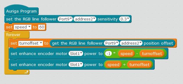
The following is an example of line following based on Auriga control board, with 180-encoded motor as the chassis:

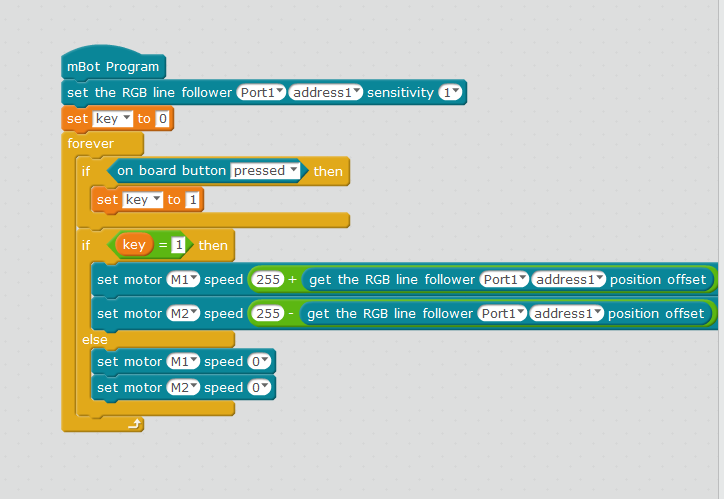
The following is an example of line following based on mCore control board, with TT motor as the chassis:

Principle
The RGB line following sensor has 4 pairs of RGB transmitters and light-sensitive receivers, as shown in the figure below:

When RGB passes through different color backgrounds, the light-sensitive receivers converts the received light information into electrical signals, and outputs specific values from the analog ports after passing through the amplifier. The software then uses the analog values of the four light-sensitive receivers as a fusion algorithm to finally calculate the deviation of the position of the output sensor module from the track. The user can directly use this offset to control the rotation speed of the left and right two motors。
Related Links
Required Specifications of mBlock
Blocks:http://km.makeblock.com/pages/viewpage.action?pageId=20121053